Reading the FFT: what the spectrum is telling you, when to dig, what to write
A field course for a CSI/AMS route analyst on pipeline pumps and motors. Everything is in the units your reports use: CPM on the x-axis, Pk velocity in in/s on the y-axis. Every figure below is a synthetic spectrum drawn to look like the AMS plot you already stare at.
How to use this (one week, 20 minutes a day)
- Day 1: Lessons 0 and 1. Learn the axes and the 60-second glance routine. Run 10 drill cases.
- Day 2: Lessons 2 to 4 (unbalance, misalignment, looseness). 15 drill cases.
- Day 3: Lesson 5 (bearings) and 6 (electrical). 15 drill cases.
- Day 4: Lessons 7 to 9 (pump hydraulics, resonance, sleeve bearings). 15 drill cases.
- Day 5: Lesson 10 (when to call it out) and the worked example on your own P1 M2A data. 20 drill cases.
- Day 6 and 7: Drill only until you are above 85% on both fault and action. Then print the cheat sheet and keep it with the analyzer.
Contents
- Reading the plot: axes, orders, resolution
- The 60-second glance routine
- Unbalance
- Misalignment
- Looseness
- Rolling-element bearings and PeakVue
- Electrical faults on motors
- Pump hydraulics: vane pass and cavitation
- Resonance and structure
- Sleeve bearings: oil whirl, rubs
- When to investigate, when to call it out, what to write
- Worked example: WIS 75N P1, M2A, 10/1/2026
- Next rung: certification and references
Lesson 0. Reading the plot
An FFT spectrum is the time waveform sorted by frequency. Each spike says "something is happening this many times per minute, this hard." Your job is to name the something.
The x-axis: CPM, Hz, and orders
- CPM = cycles per minute. Hz = CPM / 60. Your 3,579.9 RPM motor is 59.66 Hz.
- Orders = multiples of running speed. 1X = running speed, 2X = twice, 0.5X = half. Think in orders; the fault signatures are all written in orders.
- Synchronous peaks are at whole-number orders (1X, 2X, 3X...). Non-synchronous peaks are not (3.52X, 4.1X, 0.45X). Rolling-element bearing and belt frequencies are never integers.
- Read the RPM from the plot header (tach or speed-corrected). Set the harmonic cursor on 1X first, every time. Everything else is read relative to it.
The y-axis: Pk velocity in in/s
- Velocity (in/s) is the general-purpose unit from about 600 to 60,000 CPM. ISO severity limits are written in velocity.
- Pk on an AMS plot is a derived peak (rms x 1.414), not the true peak of the waveform. The ISO charts are rms. Converting: Pk = rms x 1.414; rms = Pk x 0.707.
- Overall (the "Pk = 0.675" in the header) is the energy of the whole spectrum, not the tallest line. One tall line and the overall are close; ten medium lines add up.
- Acceleration (g's) and PeakVue are for high-frequency impacting (bearings, gears, lubrication). Low in velocity does not mean fine; check the PeakVue point.
Resolution: what you can and cannot see
Resolution = Fmax / lines. At 75,000 CPM and 1,600 lines, each line is 47 CPM wide. A 2-pole motor's 2X (7,160 CPM) and twice line frequency (7,200 CPM) are 40 CPM apart: one line. You cannot separate them on the route spectrum. Rotor-bar pole-pass sidebands on a 2-pole motor are about 40 CPM from 1X: same problem. When the question is "mechanical or electrical," take a high-resolution zoom (Fmax 6,000 CPM, 3,200 lines = 1.9 CPM per line) before you write anything.
| Fmax | Lines | Line width | Good for |
|---|---|---|---|
| 75,000 CPM | 1,600 | 47 CPM | Route overview on 3,600 RPM machines, bearings up to about 20X |
| 60,000 CPM | 1,600 | 37 CPM | Route overview on 1,800 RPM machines |
| 6,000 CPM | 3,200 | 1.9 CPM | Separating 2X from 2xLF, pole-pass sidebands, beat frequencies |
| 120,000+ CPM | 1,600 to 3,200 | 75 to 38 CPM | Rotor-bar pass frequency, gear mesh, early bearing harmonics |
Lesson 1. The 60-second glance routine
Do the same seven things on every spectrum, in the same order. The routine is what makes you consistent; the fault lessons just tell you what each answer means.
- Header first. Machine, point (M1H / M2A / P1V), RPM, overall Pk. Is the overall above the band or ISO limit for this machine? Is it more than 25% above the last route? Note the answer before you look at the trace.
- Find 1X. Put the harmonic cursor on running speed. Confirm the tallest low-frequency peak is on it (if it is not, you already have a non-synchronous problem or a wrong RPM).
- Walk the harmonics. 2X, 3X, 4X... How many are there and which is tallest? One peak (1X) = unbalance territory. 2X big = misalignment. A ladder of 4 or more = looseness.
- Look between the harmonics. Anything that is not on a whole-order line? Half orders (0.5X, 1.5X) = looseness or rub. Below 0.5X on a sleeve bearing = oil whirl. Non-integer above 1X with its own harmonics = rolling-element bearing. Vane pass is at vanes x 1X (synchronous, but it is its own story).
- Look for sidebands. Little peaks evenly spaced on both sides of a bigger one. Spacing at 1X = something rotating with the shaft modulates the source (inner race, rotor bar, gear). Spacing at pole-pass = electrical.
- Look at the floor. Flat and low = good. A raised hump (haystack) = late bearing or lubrication. Grass that rises toward the right on a pump = cavitation.
- Compare. Same point, last route. Same point on the sister machine. Other directions on this bearing (H vs V vs A). Decide: Normal / Watch / Call out / Urgent (Lesson 10).
Lesson 2. Unbalance
Signature
- 1X dominant; 1X carries 80% or more of the overall.
- Harmonics (2X, 3X) under 15% of 1X.
- Radial (H and V), with H usually a little bigger than V on a horizontal machine. Axial low (under half of radial).
- Steady amplitude, steady phase.
Confirmers
- Phase: H and V on the same bearing about 90 degrees apart; inboard and outboard about in phase (static) or 180 out (couple).
- Amplitude grows with the square of speed if you can vary speed.
Look-alikes and how to separate
- Misalignment: 2X above 50% of 1X, or 1X high in axial.
- Resonance amplifying 1X: hump under the 1X, phase unstable, bump test shows a natural frequency within 20% of running speed. Do not balance until ruled out.
- Bent shaft: high axial 1X, axial phase 180 out across the bearing (both ends of the shaft).
- Eccentric rotor / air gap (motor): looks like 1X unbalance but drops instantly when power is cut.
- Overhung rotor (some pumps): 1X high radial AND axial together.
Call it out when
Overall in Zone C or above, or 1X has doubled since last route. Write: "1X dominant, radial, pattern consistent with rotor unbalance; recommend balance check after confirming with phase."
Lesson 3. Misalignment
Signature
- Angular: high axial 1X with 2X and 3X; axial on both sides of the coupling.
- Parallel (offset): high radial 2X, often 2X above 1X; sometimes 3X.
- Most real cases are a mix: 1X, 2X, 3X in both radial and axial, strongest at the coupling-side bearings (M2 and P1).
- Rule of thumb (Technical Associates): 2X over 50% of 1X = suspect; 2X over 150% of 1X = severe.
Confirmers
- Axial phase across the coupling about 180 degrees out (angular).
- Radial phase across the coupling about 180 degrees out (parallel).
- Coupling runs hot; soft foot found under a motor foot.
- Gets worse as the machine heats up (thermal growth on hot-service pumps).
Look-alikes
- 2x line frequency (7,200 CPM): sits one line from 2X on a 2-pole motor. Needs a high-resolution zoom. Electrical disappears on power-off; mechanical coasts down.
- Looseness: many harmonics, not just 2X and 3X; subharmonics; raised floor; one direction.
- Bent shaft: axial 1X and 2X with 180-degree axial phase across the SAME bearing (top vs bottom, or left vs right of the housing).
- Cocked bearing: 1X, 2X, 3X axial on ONE bearing only, phase varies around the housing.
- Coupling wear/lockup: very high harmonics (3X, 4X, 5X) axial, often with a specific order matching the coupling element count.
Call it out when
2X over 50% of 1X at a coupling-side point, or axial overall in Zone C. Write: "Axial 1X/2X/3X at the coupling end (or radial 2X dominant). Pattern consistent with angular (or parallel) misalignment. Recommend laser alignment check; confirm with 180-degree phase shift across the coupling."
Lesson 4. Looseness
Signature
- Many harmonics: 4 or more, commonly 8 to 10, with uneven heights.
- Half-order subharmonics (0.5X, 1.5X, 2.5X) as it worsens; sometimes 1/3 orders.
- Raised noise floor.
- Directional: usually vertical (the foot or cap lifts against gravity), sometimes radial on one bearing only.
Three kinds
- Structural (Type A): soft foot, loose hold-downs, cracked base, grout. 1X high, phase differs 90 to 180 degrees between the foot and the base.
- Bearing housing / cap (Type B): 2X and harmonics, cracked pedestal.
- Rotating / bearing fit (Type C): bearing loose on the shaft or in the housing, excessive clearance. 0.5X and harmonics, erratic phase, truncated waveform.
Confirmers
- Phase is erratic and changes reading to reading.
- Time waveform is clipped or flat-topped on one side (the part is hitting a limit).
- Put a hand on each foot and cap: the loose one moves.
- Compare the vertical reading at the bearing with the same spot on the base plate: a big drop across a bolted joint = loose joint.
Look-alikes
- Misalignment: stops at 3X or 4X; looseness keeps going.
- Oil whirl: a single peak at 0.42 to 0.48X, not an exact 0.5X with harmonics.
- Rub: exact half orders too, but with a broad floor and often a drop in 1X; sleeve bearings or seals.
Call it out when
4 or more harmonics with a raised floor, or any 0.5X above 0.03 in/s Pk. Looseness lets everything else get worse (it lowers the stiffness), so call it even at moderate amplitude. Write: "Multiple running-speed harmonics with raised noise floor, vertical. Pattern consistent with mechanical looseness. Recommend checking hold-down bolts, soft foot, and bearing fit."
Lesson 5. Rolling-element bearings and PeakVue
Four bearing frequencies, rules of thumb
| Name | Means | Rule of thumb (Nb = number of rolling elements) |
|---|---|---|
| BPFO | Ball pass, outer race | about 0.4 x Nb x RPM |
| BPFI | Ball pass, inner race | about 0.6 x Nb x RPM |
| BSF | Ball spin (rolling element) | roughly 2 to 3X, harmonics with FTF sidebands |
| FTF | Cage (fundamental train) | about 0.4 x RPM (sub-synchronous) |
BPFO + BPFI = Nb x RPM. Always pull the real bearing number from the data sheet and let AMS compute exact values; the rules of thumb get you from "that is a bearing" to "which race" at the screen.
Four stages
- Ultrasonic only. PeakVue just starting to rise. Nothing in velocity.
- Discrete defect frequency and harmonics appear, usually small (0.02 to 0.08 in/s). PeakVue clearly up. Watch; plan the spare.
- Harmonics grow, 1X sidebands appear, a hump forms around them. Call it out; schedule replacement.
- Peaks smear into haystacks, 1X rises, PeakVue may DROP. Urgent.
PeakVue
- PeakVue strips out the low-frequency vibration and keeps the impacts. It finds bearings (and lube problems, gear teeth, cavitation) a stage earlier than velocity.
- Severity rule of thumb from Emerson (g's Pk, PeakVue overall): at 3,600 RPM alert about 10 g, fault about 20 g; at 1,800 RPM alert 6 g, fault 12 g; at 1,200 RPM 4 g and 8 g. Check your database's own band alarms before quoting these.
- PeakVue with a clear frequency = defect. PeakVue elevated with NO frequency = lubrication or cavitation.
- A rising PeakVue trend with nothing in velocity is a stage 1 to 2 bearing: note it, shorten the interval, order the bearing.
Look-alikes
- Vane pass is a whole-number order (vanes x 1X); bearings are not. Count the order.
- Gear mesh (if there is a gearbox) is also an integer (teeth x 1X) with 1X sidebands.
- Belt frequency harmonics are sub-synchronous, non-integer, and on belt-driven units only.
Call it out when
Any non-synchronous family with 2 or more harmonics, or PeakVue above the alert level, or either has doubled since last route. Write: "Non-synchronous peaks at 3.6X with harmonics; PeakVue confirms impacting. Consistent with outer-race defect, stage 2. Recommend 2-week trend interval and planning bearing replacement."
Lesson 6. Electrical faults on motors
Signatures
| Fault | Spectrum |
|---|---|
| Stator (eccentricity, loose iron, shorted laminations) | High 2xLF (7,200 CPM) with no sidebands; uneven air gap, often temperature-related |
| Eccentric rotor | 2xLF with pole-pass sidebands; 1X with pole-pass sidebands |
| Broken / cracked rotor bars | 1X (and 2X, 3X) with pole-pass sidebands; rotor-bar pass frequency (bars x RPM) with 2xLF sidebands, high in the spectrum |
| Loose rotor bars | Rotor-bar pass frequency and 2x RBPF with 2xLF sidebands |
| Phase problem / loose connector | 2xLF with sidebands at 1/3 of line frequency (1,200 CPM); can be very high and dangerous |
Pole-pass frequency = slip x number of poles. Slip = synchronous RPM minus actual RPM. Your 2-pole motor at 3,579.9 RPM: slip 20.1 CPM, pole pass about 40 CPM. That is one line at route resolution, so you need the zoom.
The decisive test
Electrical vibration disappears the instant power is removed. Mechanical vibration coasts down with speed. If you can get a coast-down capture, you have the answer.
Confirmers
- Sidebands grow with load.
- Motor current signature analysis (MCSA) shows the same pole-pass sidebands around line frequency.
- Rotor-bar problems often show a 1X that varies (beats) over several seconds in the waveform.
Call it out when
2xLF resolved separately from 2X and above about 0.1 in/s, or pole-pass sidebands visible at more than 10% of 1X, or a 1/3-LF sideband family (phase problem) at any level. Write: "Pole-pass sidebands (40 CPM) around 1X in high-resolution spectrum, consistent with rotor bar / air-gap problem. Recommend MCSA and high-resolution follow-up at full load."
Lesson 7. Pump hydraulics: vane pass and cavitation
Vane pass (VPF = vanes x RPM)
- Always present at a low level on a healthy pump. It is a problem when it grows, when it grows sidebands, or when it jumps between routes.
- Causes: impeller-to-cutwater gap too small (or wrong impeller trim), operating far from BEP, recirculation, a plugged passage or a damaged vane, pipe strain, resonance at VPF.
- Question to ask the operator: "What flow and discharge pressure were you at?" A pump throttled to 40% flow will show vane pass that goes away at design flow.
Cavitation / starvation
- Random broadband energy, strongest at high frequency; PeakVue elevated with no discrete frequency; sounds like gravel in the pump.
- Causes: low suction pressure (NPSH), plugged strainer, suction valve, vortexing, air entrainment.
- Comes and goes with conditions; take the reading twice.
Look-alikes
- Vane pass vs bearing: vane pass is an integer order equal to the vane count.
- Cavitation vs late bearing: late bearing haystacks are centered on the old bearing frequencies and come with a rising 1X; cavitation is on the pump end only and is operating-condition dependent.
- Vane pass vs resonance: a resonance makes a BROAD peak; vane pass is sharp. If vane pass sits on a natural frequency it will be both tall and broad; the bump test tells.
Call it out when
Vane pass more than doubled since last route, vane pass with 1X sidebands, or a cavitation floor. Write: "Elevated vane-pass frequency (5X) with running-speed sidebands on pump bearings; consistent with hydraulic disturbance / off-BEP operation. Recommend verifying flow against curve and impeller clearance." Or: "Random broadband high-frequency energy on pump end, consistent with cavitation. Recommend checking suction conditions and strainer."
Lesson 8. Resonance and structure
Signature
- A wide, rounded peak instead of a sharp line.
- It does not move when running speed changes; the forcing peaks walk through it.
- Large difference between H and V at the same bearing (one direction is stiff, one is soft) is a hint that one direction is near resonance.
- Amplitude very sensitive to small speed changes.
Confirmers
- Bump test (machine off): hit it, the spectrum shows the natural frequency. Your field app's bump mode is for this.
- Phase shifts 90 degrees as the forcing frequency passes through resonance.
- Coast-down: amplitude peaks at a speed below running speed.
Why it matters
A machine running within about 15 to 20% of a natural frequency will show "unbalance" or "misalignment" that no amount of balancing or aligning will fix. Diagnose this before recommending balance work on a persistent 1X. Common sources: piping, pedestal, base plate, long shaft spans, a motor foot not grouted.
Call it out when
Any broad peak within 20% of 1X, 2X, or vane pass, or a 1X that stays high after balancing. Write: "Broad non-synchronous peak near 3,000 CPM within 20% of running speed, consistent with a structural natural frequency amplifying 1X. Recommend bump test and base/foundation stiffness check before balancing."
Lesson 9. Sleeve bearings: oil whirl, whip, rubs
Why you care
Large 2-pole motors like a 1,250 HP at 3,600 RPM are usually on sleeve (journal) bearings, not rolling-element. They do not produce BPFO/BPFI. Their failure modes show up differently.
Signatures
- Oil whirl: 0.42 to 0.48X, often taller than 1X, wanders. Caused by light load, excessive clearance, wrong oil viscosity or temperature, misalignment unloading the bearing.
- Oil whip: whirl locks onto a rotor natural frequency and stays there as speed changes. Violent; shut down.
- Excessive clearance / wear: 1X with harmonics out to 10X or more, looks like looseness, may include 0.5X.
- Rub: exact fractions (1/2X, 1/3X), many harmonics, broad floor, sometimes a DROP in 1X when it starts rubbing.
Look-alikes
- Whirl (0.42 to 0.48X, wandering) vs looseness/rub (exactly 0.5X, with 1.5X, 2.5X).
- Belt frequency on a belt drive (not on your direct-coupled pumps).
- Cage frequency FTF (about 0.4X) on a rolling-element bearing: only if the bearing IS rolling-element. Check the data sheet.
Call it out when
Any sub-synchronous peak on a sleeve bearing above about 0.05 in/s Pk. Whirl can go to whip quickly. Write: "Sub-synchronous component at 0.45X on the motor sleeve bearing, consistent with oil whirl. Recommend checking oil temperature/viscosity, bearing clearance, and alignment; re-check within days."
Lesson 10. When to investigate, when to call it out, what to write
Three questions decide every spectrum. Answer them in order and the decision falls out.
Question 1: How big is it? (absolute level)
ISO 20816-3 zone boundaries, converted to the Pk in/s your plots use (boundaries are rms; Pk = rms x 1.414). Group 1 = machines above about 400 HP (300 kW); Group 2 = 20 to 400 HP. Rigid = stiff base with the first natural frequency above running speed (most grouted baseplates); flexible = skid or structure that moves. Your 1,250 HP units are Group 1.
| Machine | Zone A newly commissioned, below | Zone B unrestricted long-term, below | Zone C short-term only, below | Zone D damage likely, above |
|---|---|---|---|---|
| Group 1, rigid | 0.13 | 0.25 | 0.40 | 0.40 |
| Group 1, flexible | 0.20 | 0.40 | 0.61 | 0.61 |
| Group 2, rigid | 0.08 | 0.16 | 0.25 | 0.25 |
| Group 2, flexible | 0.13 | 0.25 | 0.40 | 0.40 |
Values in in/s Pk, derived from the rms boundaries (Group 1 rigid: 2.3 / 4.5 / 7.1 mm/s rms, and so on). These apply to the broadband overall, not to a single line. Your database band alarms and the OEM limits override these when they exist; use ISO when nothing else is set.
- Zone A or B: level alone does not justify a call-out. Pattern and trend decide.
- Zone C: call it out with a recommendation and a re-check date.
- Zone D: call it out now, notify operations, recommend action before the next route.
Question 2: How fast is it changing? (trend)
- Within 25% of the last 3 routes: normal scatter. Say nothing.
- 25 to 100% up: note it in the report, shorten the interval. "Watch."
- Doubled (6 dB) since last route or since baseline: call it out even if the level is still Zone B. Something changed.
- Tripled or more, or climbing route after route: urgent regardless of level.
- Rising PeakVue with flat velocity: bearing or lube, stage 1 to 2. Watch, plan the spare, shorten the interval.
Question 3: What is the pattern? (some patterns get called out at any level)
| Pattern | Minimum action |
|---|---|
| Non-synchronous harmonic family (bearing), stage 2 | Watch, plan spare, 2 to 4 week interval |
| Bearing with 1X sidebands or a hump (stage 3) | Call out, schedule replacement |
| Haystacks and rising 1X, PeakVue dropping (stage 4) | Urgent |
| Sub-synchronous peak on a sleeve bearing (whirl) | Call out; urgent if above 1X |
| Half-order subharmonics (0.5X, 1.5X) | Call out (looseness or rub) |
| Pole-pass sidebands or 1/3-LF sidebands | Call out, request MCSA |
| Cavitation floor on a pump | Call out to operations (suction conditions) |
| 2X over 150% of 1X | Call out (severe misalignment) |
| Broad peak within 20% of a forcing frequency | Call out as resonance; block any balancing until bump-tested |
| Clean 1X dominant, Zone A or B, flat trend | Normal, log it |
What to write: one finding, four sentences
Every call-out in the findings report follows the same shape. The reader is a maintenance planner, not an analyst; give them the what, the why, the how sure, and the ask.
- Observation (numbers, point, direction): "M2A axial shows 1X through 6X running-speed harmonics, 4X dominant at 0.49 in/s Pk, overall 0.675 in/s Pk."
- Interpretation (pattern name, hedged correctly): "Pattern consistent with angular misalignment and coupling distress." Use "consistent with," not "is," unless you have a confirmer.
- Severity and trend (zone, change): "ISO 20816-3 Zone D for a Group 1 rigid machine; up from 0.21 on the previous route."
- Recommendation with a time: "Recommend laser alignment check and coupling inspection at the next available window, not later than 2 weeks; re-survey after correction."
Worked example: WIS 75N P1, M2A, 10/1/2026
Your own route data: 1,250 HP, 3,579.9 RPM, motor inboard axial. Run the routine on it.
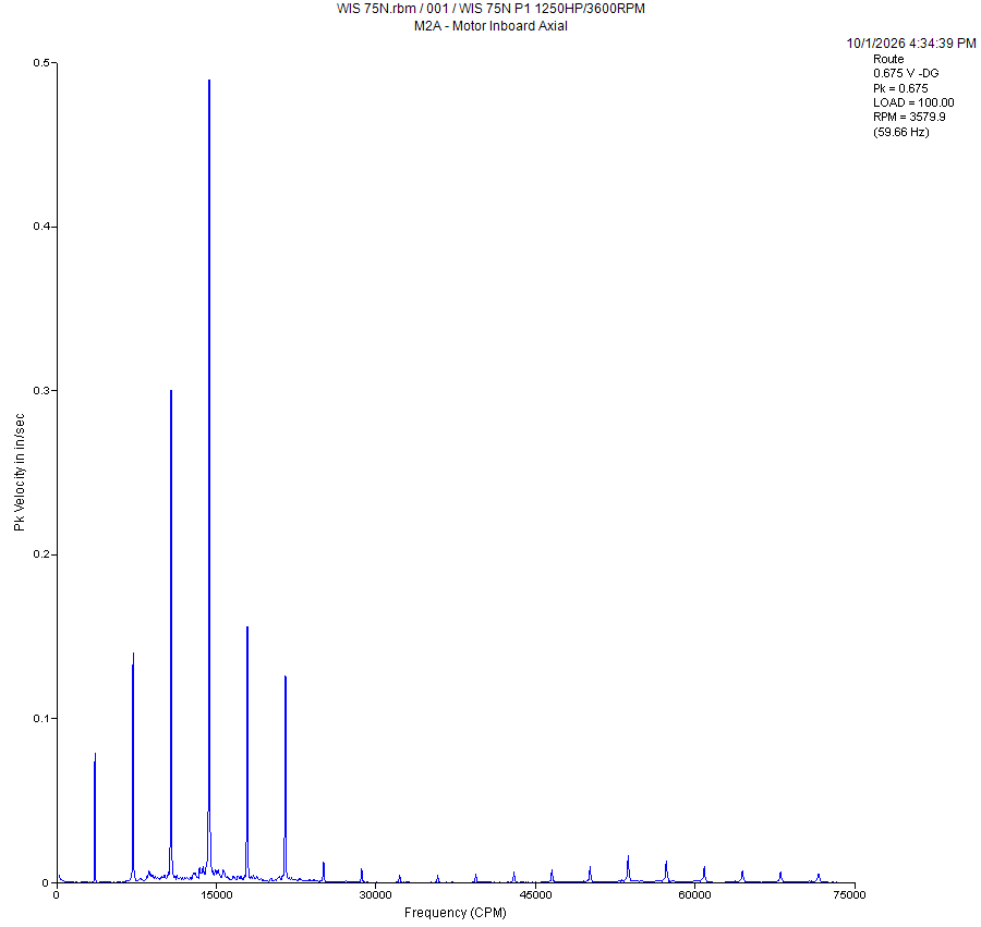
- Header. Overall Pk = 0.675 in/s. Group 1 rigid: Zone D starts at 0.40. That number alone means this gets written up.
- Find 1X. 3,580 CPM, about 0.08 in/s. Small. Unbalance is not the story.
- Walk the harmonics. 2X 0.14, 3X 0.30, 4X 0.49, 5X 0.16, 6X 0.13, then a tail of small peaks out past 20X. A full ladder, and 4X is the tallest. In the AXIAL direction at the coupling-side bearing.
- Between the harmonics. Nothing non-synchronous of any size. No bearing family, no sub-synchronous.
- Sidebands. None visible at this resolution.
- Floor. Low and flat. No cavitation, no haystack.
- Compare. You need M2H, M2V and P1A next to it. If P1A shows the same ladder, it is across the coupling. If M2H/M2V are low and only axial is high, it is angular rather than parallel.
Reading
Axial running-speed harmonics with 3X and 4X dominant at the coupling end is the angular-misalignment family, with the higher orders (4X dominant, harmonics to 6X) pointing at the coupling itself: a worn, locked-up, or mis-fitted element, or looseness in the coupling hub. A 4X peak on a coupling with 4 bolts or 4 jaws is a strong hint. Mechanical looseness is the look-alike (long ladder), but looseness is usually vertical and comes with a raised floor and half orders, neither of which is here.
Report line
What to do before you send it
- Pull M2H, M2V, P1A, P1H from the same route and state them.
- Take an axial phase pair across the coupling with the field app (Ref = M2A, Response = P1A).
- Check the coupling type and bolt/jaw count on the data sheet; if it is 4, say so.
- Look at the last three routes for M2A overall. If it was 0.2 a month ago, say "up 3x."
Next rung: certification and references
Get the credential: ISO 18436-2 Category I, then II
- Mobius Institute Vibration Analysis CAT I (online, self-paced, with the accredited exam). The industry-standard first credential; CAT II is the one that lets you sign off diagnoses. Mobius also has free intro videos (iLearnVibration) worth a weekend. Expect roughly $1,000 to $1,600 for CAT I online including exam; verify current pricing at mobiusinstitute.com.
- Vibration Institute Basic Machinery Vibration Analysis course plus the Category I exam (ANSI-accredited). Instructor-led, usually 4 days.
- Emerson Educational Services runs CSI 2140 / AMS Machinery Manager courses and their own Vibration Analysis I/II. Ask the company training budget; this one is directly on the tools you carry.
Ask your supervisor to fund CAT I this budget cycle. It is the cheapest line item that changes what you are allowed to put your name on.
Keep these next to the analyzer
- Technical Associates of Charlotte, Illustrated Vibration Diagnostic Chart. The one-sheet every analyst has pinned up; the fault tables in this course follow its layout.
- ISO 20816-3 (replaced ISO 10816-3): the severity zones above. Get the company's copy.
- Emerson PeakVue guidance (the severity-by-speed chart) from the AMS help or Emerson's knowledge base.
- Your field app (vib-field.pages.dev) for phase pairs and bump tests, the two confirmers that turn "consistent with" into "is."
This page: two-page cheat sheet, drill.
Synthetic figures are drawn by spectra.js with simplified physics for pattern training; amplitudes are illustrative. Severity values are derived from published ISO rms boundaries and common rules of thumb; database band alarms and OEM limits take precedence.